
Primary flight display (PFD)
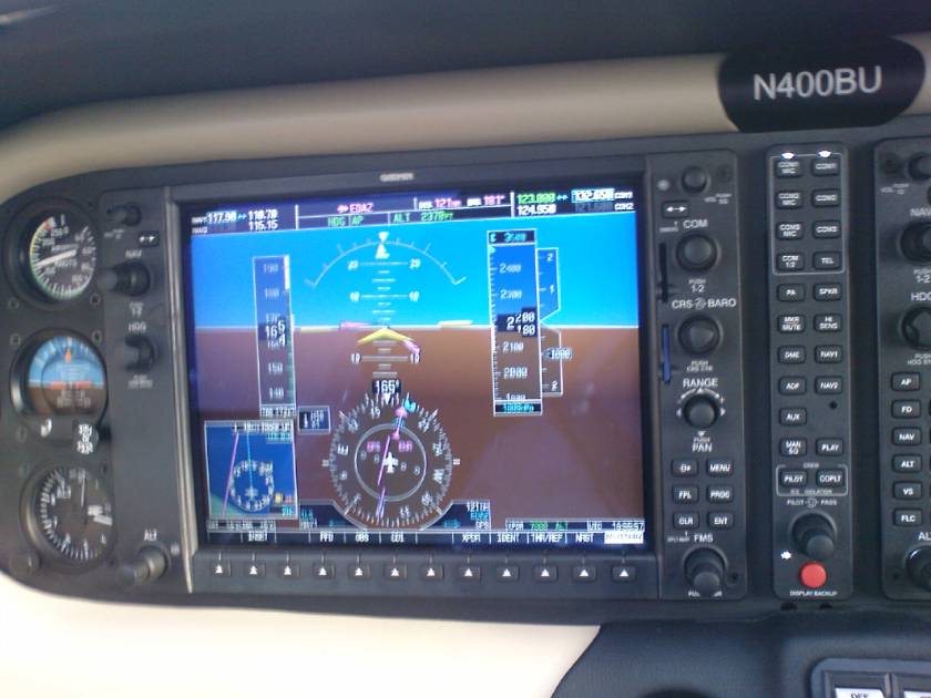
The primary flight display shows the basic flight instruments, such as the airspeed indicator, the altimeter, the heading indicator, and course deviation indicator. A small map called the „inset map“ can be enabled in the corner. The buttons on the PFD are used to set the squawk code on the transponder. The PFD can also be used for entering and activating flight plans. The PFD also has a „reversionary mode“ which is capable of displaying all information shown on the MFD (for example, engine gauges and navigational information). This capability is provided in case of an MFD failure.
Multi-function display (MFD)
The MFD usually shows engine instrumentation and a moving map.
The multi-function display typically shows a moving map on the right side, and engine instrumentation on the left. Most of the other screens in the G1000 system are accessed by turning the knob on the lower right corner of the unit. Screens available from the MFD other than the map include the setup menus, information about nearest airports and NAVAIDs, Mode S traffic reports, terrain awareness, XM radio, flight plan programming, and GPS RAIM prediction.
Implementation
The G1000 system consists of several integrated components which sample and exchange data or display information to the pilot.
GDU display
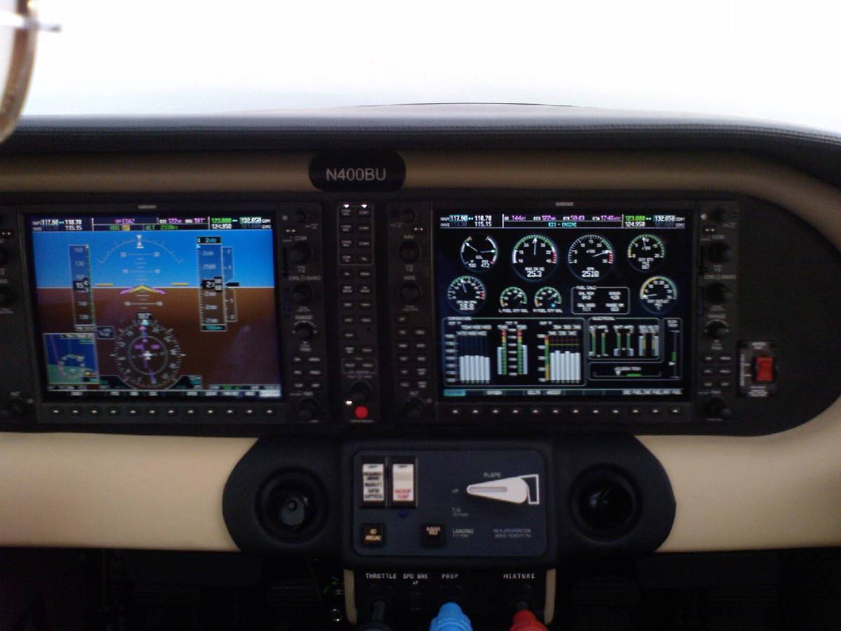
The GDU display unit acts as the primary source of flight information for the pilot. Each display can interchangeably serve as a primary flight display (PFD) or multi-function display (MFD). The wiring harness within the aircraft specifies which role each display is in by default. All of the displays within an aircraft are interconnected using a high-speed Ethernet data bus. A G1000 installation may have two GDUs (one PFD and one MFD) or three (one PFD for each pilot and an MFD). There are several different GDU models in service, which have different screen sizes (from 10 inches to 15 inches) and different bezel controls.
In normal operation, the display in front of the pilot is the PFD and will provide aircraft attitude, airspeed, altitude, vertical speed, heading, rate-of-turn, slip-and-skid, navigation, transponder, inset map view (containing map, traffic, and terrain information), and systems annunciation data. The second display, typically positioned to the right of the PFD, operates in MFD mode and provides engine instrumentation and a moving map display. The moving map can be replaced or overlaid by various other types of data, such as satellite weather, checklists, system information, waypoint information, weather sensor data, and traffic awareness information.
Both displays provide redundant information regarding communications and navigation radio frequency settings even though each display is usually only paired with one GIA Integrated Avionics Unit. In the event of a single display failure, the remaining display will adopt a combined „reversionary mode“ and automatically become a PFD combined with engine instrumentation data and other functions of the MFD. A red button labeled „reversionary mode“ or „display backup,“ located on the GMA audio panel, is also available to the pilot to select this mode manually if desired.
GMA audio panel
The GMA panel provides buttons for selecting what audio sources are heard by each member of the cockpit. It also includes a button for forcing the integrated cockpit into its fail-safe reversionary mode.
GMC/GCU remote controllers
The GMC and GCU controllers are panel-mounted modules which provide a more intuitive interface for the pilot than that provided by the GDU. The GMC controls the G1000’s autopilot, while the GCU is used to enter navigational data and control the GDU’s functions.
GIA integrated avionics unit
The GIA unit is a combined communications and navigation radio, and also serves as the primary data aggregator for the G1000 system. It provides a two-way VHF communications transceiver, a VHF navigation receiver with glideslope, a GPS receiver, and a variety of supporting processors. Each unit is paired with a GDU display, which acts as a controlling unit. The GIA 63W, found on many newer G1000 installations, is an updated version of the older GIA 63 which includes Wide Area Augmentation System support.
GDC air data computer
The GDC computer replaces the internal components of the pitot-static system in traditional aircraft instrumentation. It measures airspeed, altitude, vertical speed, and outside air temperature. This data is then provided to all the displays and integrated avionics units.
GRS attitude and heading reference system (AHRS)
The GRS system uses solid-state sensors to measure aircraft attitude, rate of turn, and slip and skid. This data is then provided to all the integrated avionics units and GDU display units. Unlike many competing systems, the AHRS can be rebooted and recalibrated in flight during turns of up to 20 degrees.
GMU magnetometer
The GMU magnetometer measures aircraft heading and is a digital version of a traditional compass. It does so through aligning itself with the magnetic flux lines of the earth.
GTX transponder
Either the GTX 32 or GTX 33 transponder can be used in the G1000 system, although the GTX 33 is far more common. The GTX 32 provides standard mode-C replies to ATC interrogations while the GTX 33 provides mode-S bidirectional communications with ATC and therefore can indicate traffic in the area as well as announce itself spontaneously via „squittering“ without prior interrogation.
GEA engine/airframe unit
The GEA unit measures a large variety of engine and airframe parameters, including engine RPM, manifold pressure, oil temperature, cylinder head temperature, exhaust gas temperature, and fuel level in each tank. This data is then provided to the integrated avionics units.
GSD data aggregator
The GSD is a data aggregator system included on complex G1000 systems, such as that found on the Embraer Phenom 100. It serves as a point of connection which allows external systems to communicate with the G1000.
Backup systems
As a condition of certification, all aircraft utilizing the G1000 integrated cockpit must have a redundant airspeed indicator, altimeter, attitude indicator, and magnetic compass. In the event of a failure of the G1000 instrumentation, these backup instruments become primary.


 LPC ICAO Level 4 Erst- und Verlängerungsprüfung in Berlin

Du muss angemeldet sein, um einen Kommentar zu veröffentlichen.